Introduction
Using a Digital Oscilloscope was a premium tool in the past; although professional equipment is still a high cost if considered for amateur use, the cost of equipment has fallen the last years allowing more people to get these instruments.
In today’s world of microcontrollers and IoT, it is not uncommon to debug serial low-speed buses, like RS232, SPI and TWI (I2C). Hobbyists and professionals need to decode manually each bit knowing the protocol. This is natural to do if you are at the first debugging stages where you need to check electrical integrity on a new design, but it gets tedious if you need to concentrate on the protocol. Purchasing a decoding module for these oscilloscopes increase the cost and many times is not an option for a one off project.
The good thing with such instruments is that they usually provide some connectivity with serial, ethernet or USB connection. Usually apart from any web based control you have the option to program the instrument through the SCPI interface. You may use any language you want if you want to access the instrument as long as you have installed the relevant VISA libraries/drivers like National Instrument’s NIVISA, or the Tektronix TekVISA (see below for links).
For those unfamiliar with SCPI (Standard Commands for Programmable Instruments), it is a standard protocol to access instruments initially based on IEEE-488 connection. Later on as more instruments used serial or ethernet connection, the required GPIB card has became obsolete and made things easier and more straight forward. The instructions available are mostly universal, but each instrument can complement these with any extensions needed to support the features unique on it.
Examples of SCPI commands:
*IDN?
ACQUIRE:STATE STOP
I started programming many instruments that way in the past using C/C++ but after switching to python I forgot about any other language in the host machine. Scripting languages offer an easy go process especially for string manipulation etc. For this reason I wrote a python script to capture signals from the oscilloscope and decode them.
In summary to access the SCPI port of a connected instrument you need the following:
1. Python Interpreter (code is written in 2.7 generation) (https://www.python.org/downloads/ )
2. TekVISA/NIVISA (or any other corresponding VISA library) package (https://www.ni.com/visa/ , http://uk.tek.com/oscilloscope/tds7054-software )
3. PyVISA module (https://pyvisa.readthedocs.io/en/stable/ )
4. The Capture/decode python script.
Now under Windows you may use the executable which is a compiled python script (with GUI2Exe). In this case you will need only the VISA installation and the tool itself (no need for python+pyvisa as these are included in the compiled program).
How it works
The tool captures the signals from the oscilloscopes in a CSV file. As I use an old TDS3012B DPO from Tektronix, I only have 2 available channels to capture. This is fine for capturing RS232 or TWI signals, but for SPI you may need to perform multiple runs to capture 2 data lines and CS along with the clock, with you ending up changing probes for each run, but this is better from nothing.
Oscilloscopes with more channels would of course capture more signals and avoid this hick-up. The script is made and tested on this particular oscilloscope, but it should work in most other instruments maybe with slight modifications. If you need to capture more channels then you still need to modify the script to save the extra channels on the CSV and in addition to add to the SPI decode module the extra traces to decode. But this is why we have open source right?
Keep in mind that the script decodes from the CSV file (and not directly from the instrument). Thus if you have old (or test) captures you may instruct it to use these instead of accessing an instrument. This helps for off-line decoding or testing the script.
After the signals are captured, the script performs a thresholding according to the set logic standard like TTL, CMOS, LVCMOS etc.
Then it decodes the signal according to the requested protocol and displays the decoded output on screen.
To keep the script simple, we setup the oscilloscope manually to capture the signals fully (with the required time-span, sampling etc) and we leave it running. Triggering should be to Normal mode (not Auto). When we need to capture the waveform we can either run the script which stops acquisitions or we can stop manually and still use the script to acquire and decode the signals.
Let’s see some examples.
RS-232 Decoding
Running the command:
DSOCapture.py -b RS232 -l TTL -a 115200 -i CaptureRS422_LVCMOS.csv -n 0
We decode a file with data already acquired to a file.
We need to define the baud rate, the voltage level and polarity (positive or reversed).

The decoder displays the resulted characters along with the Start-Stop and Parity bits. In addition a VCD file is exported that we can view with GTKWave.

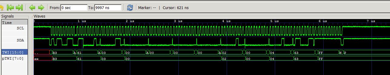
TWI Decoding
In TWI mode the parameters are more simple as TWI is clocked so we do not need to define sampling period for each character.
DSOCapture.py -v -b I2C -i CaptureI2C.csv

Again the results are shown in the Command Prompt, showing Start-ACK-Stop conditions.
In addition the VCD file provides a graphical view.

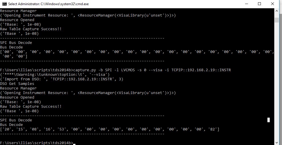
SPI Decoding
In this example we acquire the signal from the instrument (which is the more common way to do it). Every acquisition will store the .csv file with the data, if you need it. However you will need to copy it since the next acquisition will overwrite it.
DSOCapture.py -v -b SPI -t 3 -visa -i TCPIP::192.168.2.226::INSTR -f capture.csv

Development Methodology
Now the interesting thing is that I used TDD (Test Driven Development) methods to create this script. To help me in this process I used the pytddmon.py script. So when developing you just need a command prompt or shell in the directory holding the script and run pytddmon.py (should be at the same directory). See picture below.


You may download pytddmon from here. Alternatively you may use:
pip install pytddmon
Next thing is that I created the test cases for each module. Initially I used real data captured on my oscilloscope or used similar values to test the various cases. For example thresholding the incoming stream is more challenging than just compare and output a logic value. As you pass through the transition phase from 0-1 or 1-0 then some values may trigger multiple transitions on each edge. In this case you need to perform hysteresis ( link ) to avoid it (as the electronics do as well).
After the signals have been interpreted to logic levels (or edges as well, as TWI uses the edges), then the thresholded outputs are passed to the corresponding serial bus analyzer.
Limitations
The script does work well but there are limitations mainly due to the hardware (Digital Oscilloscope) which is worth to mention.
RS232
The problem with RS-232 is that it is an asynchronous transmission. To better state the problem, there is no clock transmitted or derived from the data. It is assumed that the receiver has a similar clock within a certain range to capture and decode the transmission.
If you need to capture a long stream of bytes and the scope does not have big memory you will find yourself limited on what can be captured. As the scope’s memory is not sufficient to hold a longer time period with much detail the decoded data may be scrambled (usually after a few bytes). To overcome this you may need to decrease the time span of the data or use an instrument with sufficient memory capacity to hold accurately the signal transitions.
TWI
This kind of bus uses edge signalling to determine certain protocol states (like Start/Stop conditions). If the sampling of the scope is not sufficient you may get bad decoding of the signals. Although not so severe as RS-232 protocol, this will happen only if you stress the instrument.
SPI
SPI bus is a clocked transmission so sampling is not much an issue as in the other protocols. However because you usually need three lines (SCK, MISO, MOSI), you need extra effort to read all lines with a two channel scope. As this script was built around TDS3012B, it captures only two channels. If you have an instrument with more channels available I would recommend to modify the script and capture the extra channels.
Summary
Improvements to the script can be performed, but as I am busy doing other things, I currently do not plan to do any additions. In any case any ideas are welcome and at some point may integrate them.
I created this script some time ago, initially for TWI, then I added RS232 and finally the easiest part SPI. I completed the whole script in about a two week time (with full functionality) and it was pretty easy. If I had to work without TDD, I would need to capture all the possible variations on my scope and debug a much larger codebase at the time.
You may find a compiled Python executable here
You may find the source tree in BitBucket.